A number of different groups have suggested a range of variants to the CGM although few of them have been formally described or validated in the academic literature.
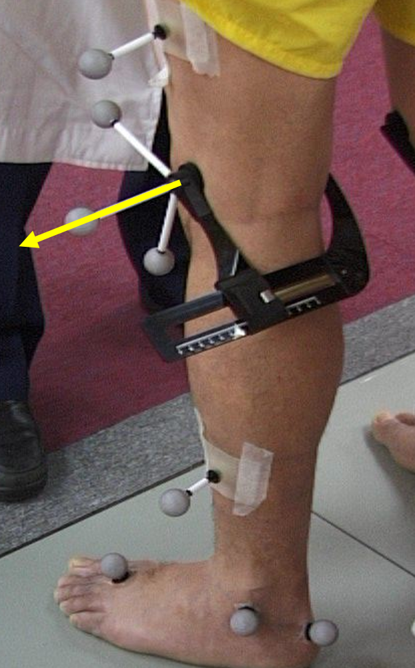
Knee Alignment Device.
Implementation of the original model assumed that the thigh and tibial wands could be placed accurately which proved extremely difficult in practice. To overcame this an alignment jig was developed that could be applied to the patient’s knees in standing in such a way that a wand protruding laterally (the yellow arrow superimposed on the figure below) runs parallel to the knee joint axis.
If the KAD is found then a number of offsets can be calculated from data collected during a static calibration trial and then applied to the model for all subsequent walking trials.
- The femur rotation offset specifies by what angle the femur wand marker likes out of the coronal plane of the femur.
- The shank rotation offset specifies by what angle the tibia wand marker lies out of the coronal plane of the tibia. In order to work this out, however, the system needs to know how much tibial torsion is present (the angle between knee joint axis and ankle joint axis projected onto the transverse plane of the tibia). This is measured as part of a brief physical examination conducted before the session.
Medial epicondyle and malleolar markers
The KAD was developed when the small number of cameras that could be used to make measurements made it impossible to detect the position of medial knee and ankle markers. Once these became available placing medial and lateral epicondyle and malleolar markers became a sensible alternative for indicating the position of the knee and ankle joint axes during static calibration as a basis for calculating the same offsets as had previously been derived from the KAD.
Some centres already using the KAD used it to define the knee joint axis and a medial malleolar marker to define the ankle axis. In this way tibial torsion could be calculated from marker positions as either an alternative to a physical examination measure or as a confirmation of it.
Dynamic knee calibration
An alternative to the KAD is presented by analysing how the knee moves in a dynamic calibration trial to determine the location of the physiological knee joint axis. Baker et al. 1999 proposed finding the axis thigh rotation offset that minimises the variance of the knee ab/adduction curve using a technique he called DynaKAD. A range of other, more sophisiticated techniques have since been suggested (e.g. Schwartz and Rozumalski, 2005; Ehrig et al.). Recent validation studies suggest that DynaKAD gives the closest agreement to both ultrasound (Passmore and Sangeux, 2016) and low does biplanar radiographic measures of anatomical knee joint axis (Sauret et al. 2016).
Pelvic width from ASIS markers
As originally described pelvic width (the distance from one ASIS landmark to the other) was measured on physical examination. An alternative is to measure the distance beween the corresponding markers. The accuracy of this process clearly depends on the accuracy of marker placement.
Three dimensional foot segment
The heel marker was originally only intended to allow the calculation of foot offsets during a static calibration trial. Leaving the marker on during walking, however, provides a reference point allowing in/eversion of the foot to be calculated (rotation about the long axis of the foot).
Footflat and footwear pitch
Placing the heel marker at the correct height to calculate the plantarflexion offset during the static trial is not required if the patient can stand with their foot flat on the floor. If this is the case then calculating the offset with the true horizontal plane is more accurate and often used. A variant to this for people wearing shoes is to measure or estimate the pitch of the shoe (the angle that the plantar surface on the foot inside the shoe makes with the sole of the shoe outside it) and entering this as an offset to be taken into account when calculating the plantarflexion from the horizontal plane.
Upper body model
As noted previously Vicon released an upper body model as part of PiG. This has never been properly validated and is beyond the scope of this documentation.