Having defined segments in terms of the underlying anatomy it is then possible to determine how markers can be placed in order to determine the position and orientation of those segments. Generally speaking it takes at a minimum of three points to define a segment but assuming ball and socket joints means that one of these points can be the joint defined within the proximal segment. When the model was developed this was essential to minimise the number of markers given the limited number of markers that measurement systems of the time where able to detect. It is still a useful feature to minimise the amount of time taken in placing markers.
Estimating the location of joint centres within the segments is based upon a number of anthropometric measurements made during a brief clinical examination prior to data capture. A further document is being prepared giving a more detailed description of how these measurements should be made.
The CGM requires the use of wand markers on the femur and tibia segments. Over recent years there has been a tendency to replace these by skin mounted markers in approximately the same positions. Such markers can be very close to the line between the other two markers on the segment and make the segment definitions highly sensitive to soft tissue artefact and marker placement error. Loosely attached wands can introduce “wobble” but this can generally be avoided by taping over the base plates over the whole circumference on the thigh or calf.
Theory of Marker Placement
The table below is intended to given an overview of the theory of where markers need to be placed. A further document is being prepared giving a more practical guide to marker placement.
Pelvis
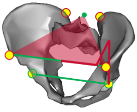
Markers are placed over both ASIS and PSIS in order that they lie in the plane containing the anatomical landmarks.
A set of equations are used to estimate the location of the hip joint within the pelvic coordinate system.
Femur
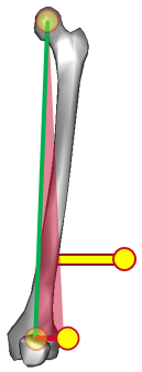
The hip joint centre within the femur is coincident with that within the pelvis.
A marker is placed over the lateral femoral epicondyle and another on a wand on the lateral thigh in such a way that the two markers and the hip joint centre lie within the coronal plane of the femur.
The knee joint centre is to be defined such that it, the hip joint centre and the epicondyle marker form a right angle triangle within the coronal plane of the femur with a base of half the measured knee width.
Tibia
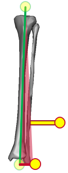
The knee joint centre within the tibia is coincident with that within the femur.
A marker is placed over the lateral malleolus and another on a wand on the lateral leg in such a way that the two markers and the knee joint centre lie within the coronal plane of the tibia.
The ankle joint centre is to be defined such that it, the knee joint centre and the malleolar marker form a right angle triangle within the coronal plane of the tibia with a base of half the measured ankle width.
Foot
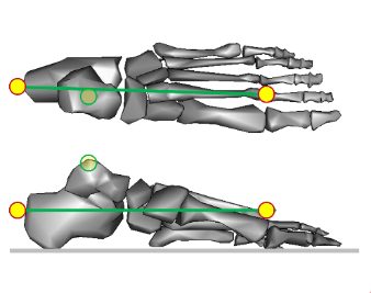
The ankle joint centre in the foot is defined to be coincident with that with the tibia.
A marker is placed on the forefoot.
Another is placed on the posterior aspect of the heel for the static trial such that the line between the two makers is parallel to the long axis of the foot. The angles between this and the line from the ankle joint centre to the forefoot marker in the sagittal and horizontal planes are calculated. The heel marker is not used in walking trials but the offsets are used to estimate the alignment of the long axis of the foot based on the line between ankle joint centre and forefoot marker.